There are 2 x 16-bit timers (TIMER 1 and TIMER 2). These operate by being preset to the required count and then they count DOWN to zero.
A flag is set when zero is reached. This may cause an interrupt if the respective enable bits are set.
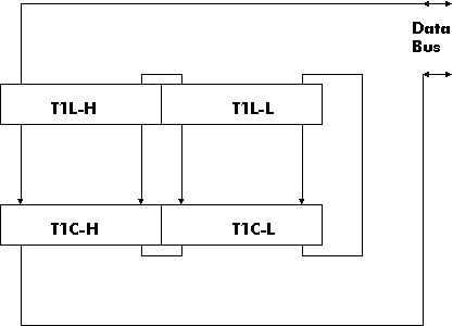
The counters have two parts, the counter (T1C) and its latch (T1L).
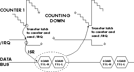
Since our 8-bit microprocessor can only load one half of the counter at a time and since two successive writes may be around 10 microseconds apart, then there would be problems in setting the counter to a precise value as it is usually decrementing all the time.
So a mode is provided where the latch may be written without affecting the counter.
In this way, T1L-L (the low order 8-bits of the latch) is written first. Then when T1L-H is written to, T1C-H is simultaneously loaded and T1C-L is loaded from T1L-L (mode 0101). Thus a 16-bit parallel load of the counter is achieved.
When the counter reaches zero, it can automatically reload itself with the value held in the latches.
When Timer 1 reaches zero, it sets the flag IFR6 and this will generate an interrupt if IER6 is also set.
At this point, the timer may be disabled (i.e. generates no further interrupts) or it may reload itself from the latches and continue to decrement. This option may be used to generate equally spaced interrupts (e.g. for use as a real-time clock).
Also, each time Timer 1 reaches zero, PB7 may be programmed to change state. This can be used to generate a clock signal on PB7.
	ACR5 = 0;	interval timer, interrupt on reaching zero

	ACR5 = 1;	uses PB6 as a clock input and decrements

			on each negative transition with an

			interrupt on reaching zero.
The shift clock has three possible sources:
(a) Timer 2 timeout
(b) system clock (E)
(c) external clock on CB1
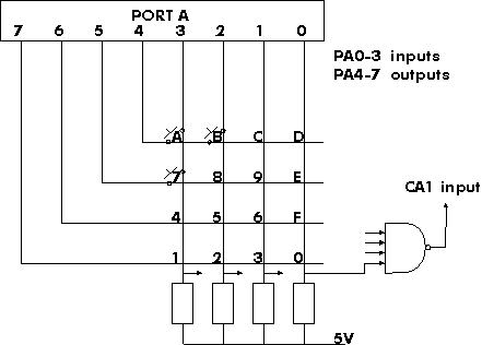
If PA4-7 are set to zero, then any key pressed in the matrix will pull
the corresponding input line LOW
i.e. a READ from PORT A will no longer give $F on the lowest 4 bits.
In addition, with the NAND gate shown, any key pressed will cause an
interrupt to be generated via CA1 input. This will alert the
microprocessor to read Port A to determine which switch has been pressed.
e.g. if switch '8' is pressed,
PORT A reads 00001011 = $0B
This tells us that a key has been pressed and in this case, it is one of the keys in column '2'.
Generally, more than one key may have been pressed and more than one column may read as zero.
To identify the exact key (or keys) pressed, we must poll the individual rows of the matrix.
e.g. writing 0111 to PA7-4, polls keys 1,2,3,0
If any of these keys are pressed, PA3-0 does not read '1111'.
Then if 1011 is written to PA7-4, keys 4,5,6,F are polled,
when 1101 is written to PA7-4, keys 7,8,9,E are polled
and finally when 1110 is written to PA7-4, keys A,B,C,D are polled.
In our example for switch '8', when PA7-4 contains 1101 then PA3-0 reads as 1011. The code in Port A (11011011) identifies that key '8' is pressed. A look-up table will normally be used to convert this number into a meaningful key number. This is preferred to a series of CMP and BRANCH instructions.
There are practical problems not dealt with here. For example, switch bounce is a real problem. It is normal, when a key has been identified as being pressed, to generate a software delay and to read the key again to reduce the effects of noise.